 Flight Control Mechanisms in a Simple Helicopter
 On an airplane these are controlled by elevators, airlerons, and rudder, respectively. But helicopters have none of these. On a helicopter, pitch and roll are controlled by changing the pitch of the blades of the main rotor through a part of their sweep, causing the main rotor plane to tilt because of uneven lift. This in turn tilts the helicopter. Yaw is controlled by changing the pitch of the blades on the antitorque rotor.
How Helicopter Controls WorkSitting in the cockpit of a helicopter, the flight controls are described as follows. In your left hand, there is a lever beside the seat, kind of like a parking break. You can lift it up, or push it down. On the handle of this lever, especially in the old days, is a twist grip throttle control for the engine. This lever is the collective pitch lever. It changes the pitch of the blades of the main rotor throughout their sweep. Your feet go on two peddles just like in an airplane; these control the pitch of the blades of the anti-torque rotor. In your right hand is a stick that has a free range of motion, just like the control stick of an airplane. This is the cyclic pitch control. It changes the pitch of the blades of the main rotor through part of their sweep.
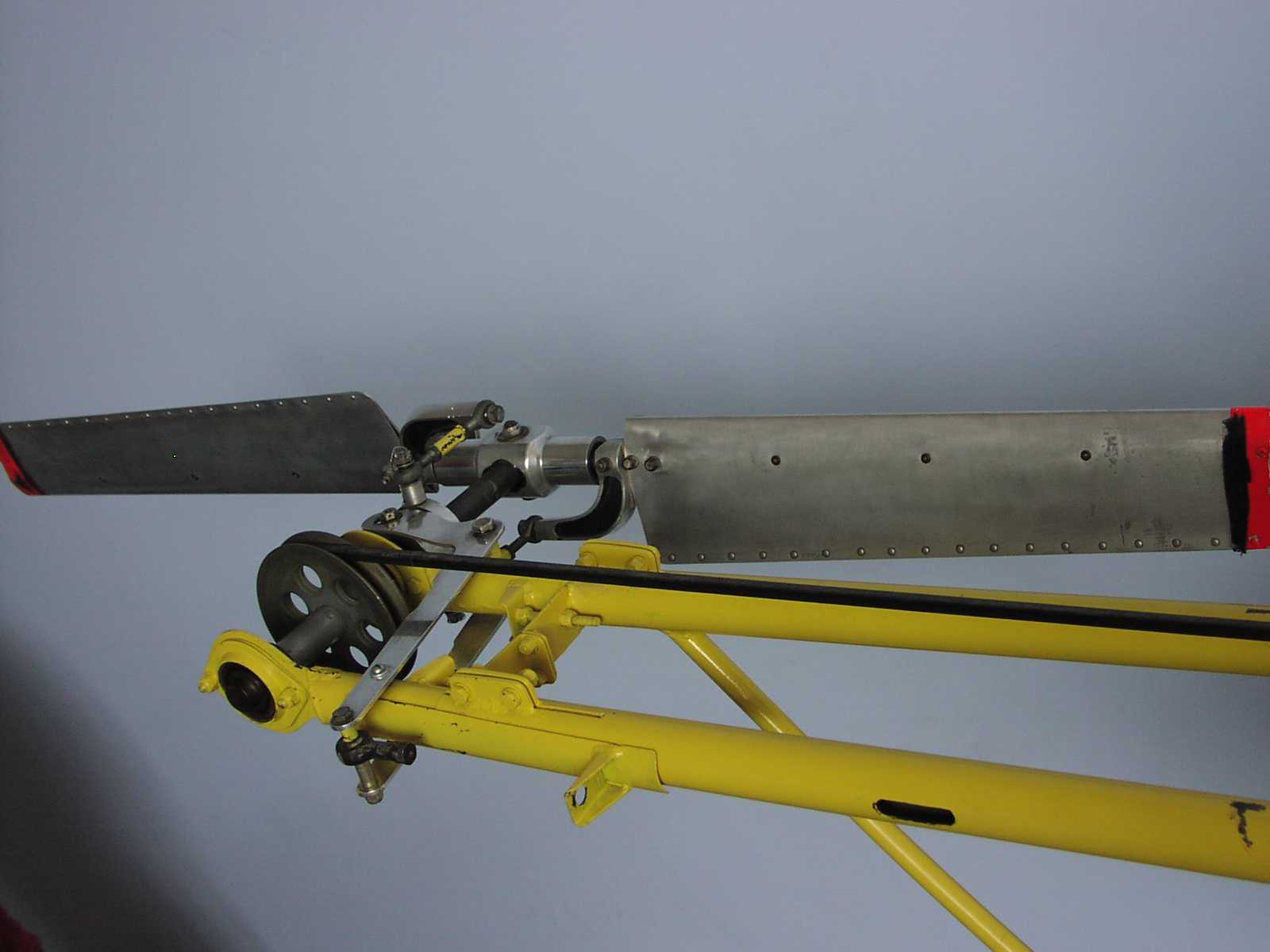
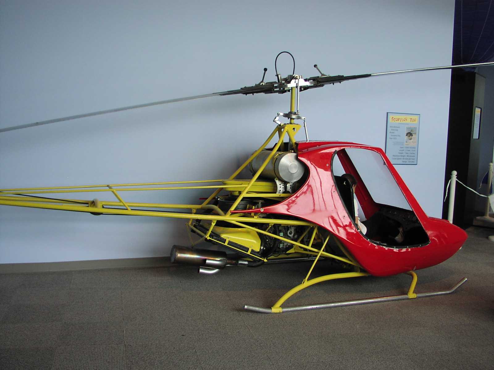
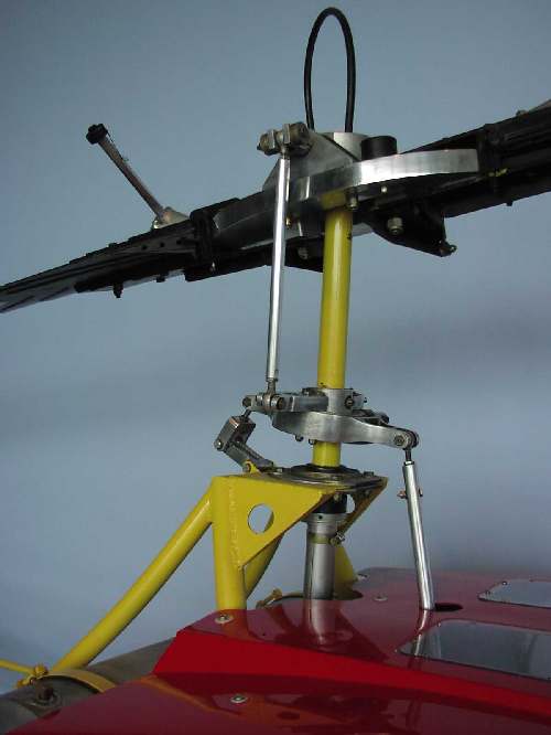
What the Linkage Looks Like on a Simple HomebuiltThe Rotorway International Scorpion Too was one of several attempts by a small manufacturer to market an inexpensive helicopter that you could build and learn to fly out of your back yard. To stand in front of an example of this model and contemplate actually going up in it is a fairly sobering experience, especially after a careful inspection . . . nevertheless it was at least moderately successful, and RI has continued to develope and improve their product line and is still in business today. The Rotorway International story is well documented elsewhereThe wonderful thing about the Scorpion Too is that you can see exactly how the controls and associated linkage interact with the control surfaces. Very little of the aircrafts mechanical system components are hidden behind body panels. The antitorque rotor pitch linkage is easiest to understand; it is depicted in these pictures:
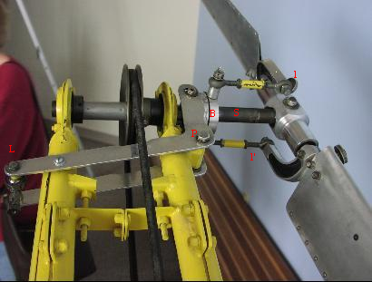
Missing linkage pushes or pulls the lever L, which pivots at p, sliding bearing b along shaft s which pushes pitch levers l and l'. Collective pitch is controlled by means of a housed cable such as that that controls the clutch on an old motorcycle. The cable comes up through the very center of the main rotor shaft, and is visble looping up out of the rotor and down to the linkage, shown in figure 2, Below:
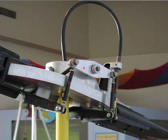 The cable innerwire pushes or pulls on lever L, which directly holds the blade pitch for that side of the two bladed rotor. As lever L is moved, Rocker plate R pivots at P, which moves lever L' in an equal and oposite direction, which trims the opposite rotor to have the same pitch. Note that turnbuckles T and T' are adjustable, so that the rotor can be finely tuned for balenced lift - this is roughly analogous to adjusting the alignment and centering the steering wheel on the front end of an in an automobile, but much more critical since different rotor trim throughout the sweep of rotation is probably destructive. The cyclic pitch is more mysterious. In this example, the cyclic pitch linkage is disconntected, so you cannot just move the cyclic in the cockpit and see what it does, but you can look at the linkage and put two and two together as best you can. Unfortunately, the linkage beneath and to the rear of the cockpit is a bit complicated:
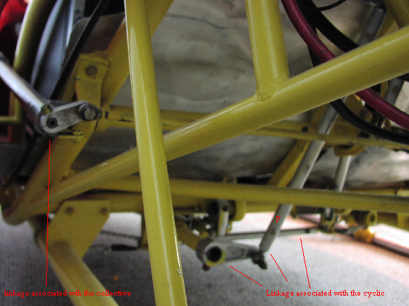 The only thing obvious to me so far is that the cyclic control moves pushrod P along its long axis. Pushrod P is easily followed to the rotor head: 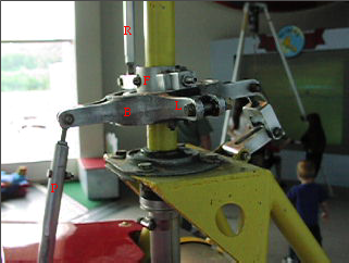 At the rotorhead, pushrod P moves a kind of round bearing that the main rotorshaft runs inside. P merely rocks B in the for and aft direction. B is stationary but follower bearing F and cyclic pitch rod R rotate with the main rotor. R is seen to change pitch varyingly though the rotor sweep according to the attitude of B. Download and view the quicktime movie. (Sorry about the format! A free player is available ... I wish I could convert these to something natively supported.) If bearing B can only be rocked fore and aft, how to we move cyclic in the remaining dimension? It is not enough just to control roll, or just to control pitch; we must be able to do both with the cyclic. As elsewhere on this example, there is missing linkage here in the rotorhead; there should be another rod like P attached to the rotorhead at pivot point L. This missing rod P' would rotate B about the roll axis, and together with the effect of pushrod P analysed above that rotates B about the pitch axis, which will give full cyclic control of the rotor plane.
 Notice the additional missing linkage evident in this picture. Immediately above pivot point L is a post that looks like the lower linkage joint for a pushrod to match R. Normally on rotor heads of this type, there are two such rods, for example on a Bell 204 (Huey).
|
||||